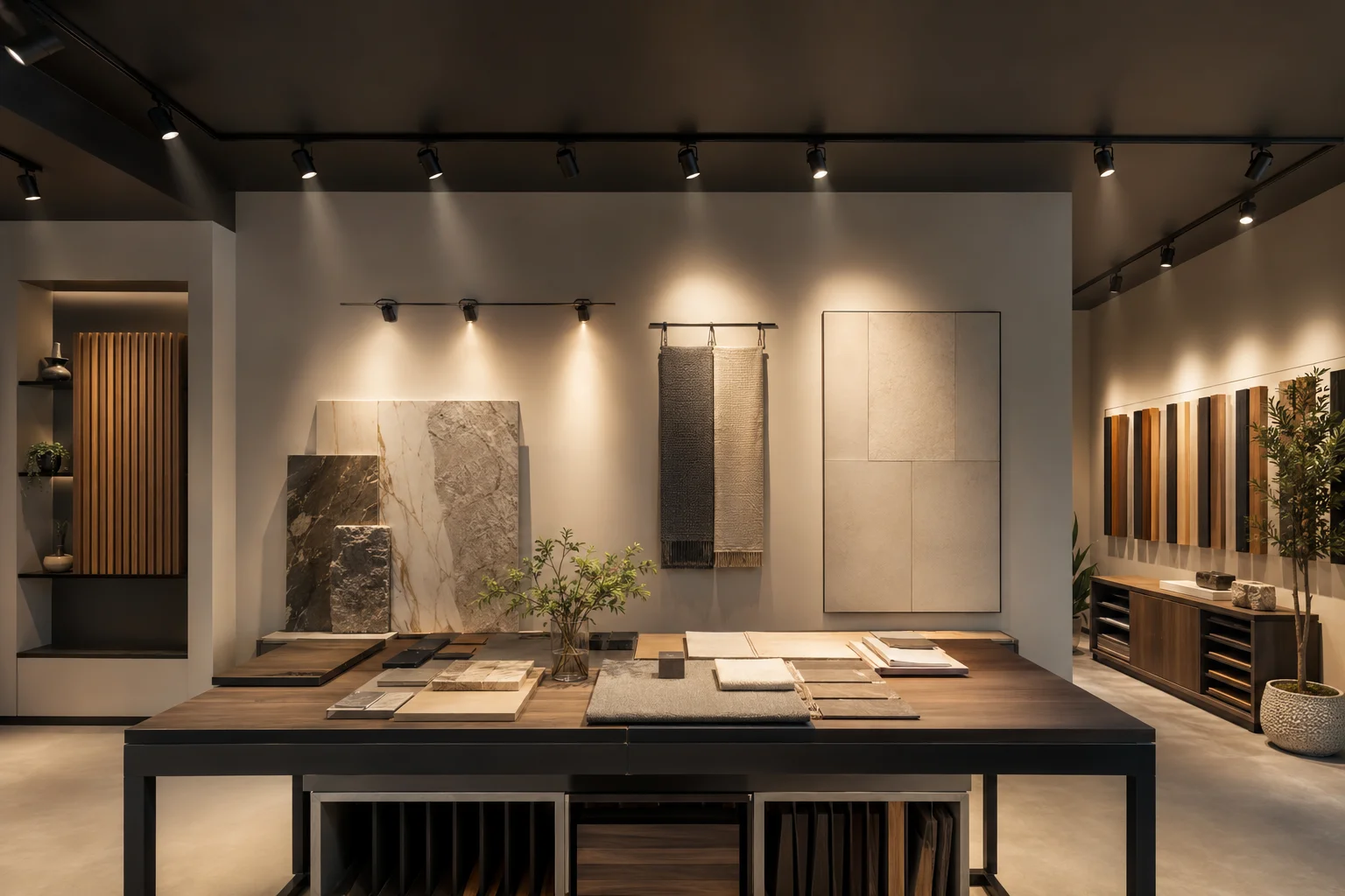
Two luminaires can produce the same number of lumens and still create completely different spaces.
One may form a tight pool of light on a product display or work surface. The other may spread its output broadly across a room. The total quantity of light can be similar, but the concentration, coverage, contrast and visual effect are not.
The difference is created by the optical distribution of the luminaire, and beam angle is one of the most useful ways to begin describing that distribution.
Beam angle affects where light lands, how large the illuminated area becomes at a given distance and how intense the centre of the beam may appear. It influences accent lighting, task visibility, uniformity, glare, fixture spacing, light spill and the atmosphere of a space.
However, beam angle is not a complete lighting design. It must be interpreted together with luminaire lumens, candela values, mounting geometry, aiming, photometric data and the visual task.
Beam angle marks a 50% intensity boundary. It does not define a hard edge, a complete distribution or a guaranteed lux level.
This guide explains how to read the number correctly and how to use it as part of a practical, performance-led lighting decision.
What a beam angle really measures
Beam angle is expressed in degrees and describes the angular width of the main beam around its optical axis.
The CIE International Lighting Vocabulary defines it as the full angle between the two directions where luminous intensity has fallen to 50% of the centre beam intensity. This is important for two reasons:
- The stated value is the full included angle, not the angle measured from the centre line to one side.
- The boundary is based on intensity, measured in candela, rather than on a visible hard edge.
If a luminaire has a 30-degree beam angle, its half-angle is 15 degrees on either side of the beam axis. At those two nominal beam boundaries, intensity is 50% of the centre beam value.
Light does not suddenly stop outside that boundary. The intensity normally continues to decline through a wider spill region. Depending on the luminaire and the terminology being used, this wider region may be described as the field, beam spread or useful spill.
The CIE defines beam spread using a 10% threshold for illuminance on a plane normal to the beam axis, while noting that the term is sometimes calculated at 50%. This is why a catalogue should state the definition behind its angle. A 50% beam angle and a 10% beam spread are not interchangeable.
 Figure 2. A conceptual smooth intensity profile shows the 30-degree beam boundary at 50% of centre intensity and the wider 10% spill boundary
Centre beam intensity, field light and the soft edge
The centre beam intensity is the luminous intensity measured on the optical beam axis. It is expressed in candela.
Moving away from that axis, the intensity usually reduces rather than remaining perfectly flat. The resulting beam can have:
- A strong central peak with rapid falloff
- A broad, relatively even plateau
- A soft-edged distribution
- Rings, striations or secondary peaks
- Different horizontal and vertical spreads
- An intentionally asymmetric shape
Beam angle only identifies two threshold points in one plane. It does not reveal the full shape between those points or the amount of light outside them.
This explains why two luminaires with the same nominal beam angle can still look and perform differently. One may have a smooth transition into the surrounding field, while another may create a pronounced hotspot and a sharp contrast at the edge.
The complete luminous-intensity distribution, not the headline angle alone, determines the real result.
How the optic shapes the beam
An LED package is a small source, but the finished luminaire’s distribution is created by the complete optical system.
Reflectors, lenses, diffusers, shields, louvres and the position of the LED relative to these components can redirect, spread, soften or limit the light. A well-engineered optic controls more than width; it manages intensity, efficiency, cutoff, beam quality and the transition from the main beam into the surrounding field.
Narrow optics
A narrow optic concentrates a greater portion of the available light into a smaller angular region. This normally creates higher peak candela and a smaller pool of light at the target.
Narrow beams are useful for:
- Accent lighting and visual hierarchy
- High-ceiling or long-throw applications
- Artwork, merchandise and architectural features
- Focused task areas
- Signs, facades and selected outdoor targets
Medium optics
A medium beam balances focus and coverage. It can provide useful task illumination while retaining enough spread for comfortable transitions and overlap.
Typical uses include:
- Retail shelving and counters
- Hospitality tables and feature areas
- Residential or commercial downlighting
- Workstations and selected production tasks
- General lighting from moderate mounting heights
Wide and diffuse optics
A wide optic distributes light over a larger angular field. This supports broad coverage and can improve uniformity when the luminaire spacing and room geometry are appropriate.
Typical uses include:
- General ambient lighting
- Low- to medium-height interiors
- Corridors and circulation areas
- Broad ceiling or wall illumination
- Open industrial and commercial spaces
These categories are descriptive rather than universal. A manufacturer may call 24 degrees a spot, another may call it a narrow flood, and a specialised optic may not fit a simple circular category at all. Compare measured data rather than relying on names.
The NEMA classification: useful, but check the threshold
The LEDVANCE guide summarises a commonly used NEMA-style floodlight classification:
| Angular range | NEMA type | Description |
| 10-18 degrees | 1 | Very narrow |
| 18-29 degrees | 2 | Narrow |
| 29-46 degrees | 3 | Medium narrow |
| 46-70 degrees | 4 | Medium |
| 70-100 degrees | 5 | Medium wide |
| 100-130 degrees | 6 | Wide |
| 130 degrees or more | 7 | Very wide |
This classification is especially useful for floodlighting and may be stated separately for the horizontal and vertical planes, such as a narrower vertical spread with a wider horizontal spread.
The important caution is that NEMA field-spread classifications are commonly associated with a wider threshold than the CIE 50% beam-angle definition. Product literature is not always consistent in its terminology. Before comparing a NEMA type with a stated beam angle, confirm:
- Whether the angle is measured at 50% or 10% of peak intensity
- Whether it describes the horizontal, vertical or both planes
- Whether the distribution is symmetrical or asymmetric
- Which test data or photometric file supports the classification
The same number can describe different boundaries if the measurement convention is not stated.
From angle to beam diameter
For a symmetrical beam aimed perpendicular to a flat surface, the nominal beam diameter can be estimated from the beam angle and the distance from the luminaire to that surface:
Beam diameter = 2 x distance x tan(beam angle / 2)
The distance should be measured from the luminaire’s photometric centre to the actual target plane. For a desk or workbench, this is not the same as the ceiling-to-floor height.
The geometry gives the following approximate diameters:
| Nominal beam angle | Diameter at 3 m | Diameter at 6 m |
| 15 degrees | 0.79 m | 1.58 m |
| 30 degrees | 1.61 m | 3.22 m |
| 45 degrees | 2.49 m | 4.97 m |
| 60 degrees | 3.46 m | 6.93 m |
| 90 degrees | 6.00 m | 12.00 m |
This is a geometric estimate of the nominal 50% beam boundary. It does not predict uniformity, edge softness, spill light or lux. It also assumes a symmetrical beam, perpendicular aiming and a flat surface.
If a luminaire is tilted, the footprint stretches and becomes more elliptical. If the target is a wall, shelf, facade, rack face or irregular object, the useful pattern must be considered in that geometry.
Centre beam intensity, field light and the soft edge
The centre beam intensity is the luminous intensity measured on the optical beam axis. It is expressed in candela.
Moving away from that axis, the intensity usually reduces rather than remaining perfectly flat. The resulting beam can have:
- A strong central peak with rapid falloff
- A broad, relatively even plateau
- A soft-edged distribution
- Rings, striations or secondary peaks
- Different horizontal and vertical spreads
- An intentionally asymmetric shape
Beam angle only identifies two threshold points in one plane. It does not reveal the full shape between those points or the amount of light outside them.
This explains why two luminaires with the same nominal beam angle can still look and perform differently. One may have a smooth transition into the surrounding field, while another may create a pronounced hotspot and a sharp contrast at the edge.
The complete luminous-intensity distribution, not the headline angle alone, determines the real result.
How the optic shapes the beam
An LED package is a small source, but the finished luminaire’s distribution is created by the complete optical system.
Reflectors, lenses, diffusers, shields, louvres and the position of the LED relative to these components can redirect, spread, soften or limit the light. A well-engineered optic controls more than width; it manages intensity, efficiency, cutoff, beam quality and the transition from the main beam into the surrounding field.
Narrow optics
A narrow optic concentrates a greater portion of the available light into a smaller angular region. This normally creates higher peak candela and a smaller pool of light at the target.
Narrow beams are useful for:
- Accent lighting and visual hierarchy
- High-ceiling or long-throw applications
- Artwork, merchandise and architectural features
- Focused task areas
- Signs, facades and selected outdoor targets
Medium optics
A medium beam balances focus and coverage. It can provide useful task illumination while retaining enough spread for comfortable transitions and overlap.
Typical uses include:
- Retail shelving and counters
- Hospitality tables and feature areas
- Residential or commercial downlighting
- Workstations and selected production tasks
- General lighting from moderate mounting heights
Wide and diffuse optics
A wide optic distributes light over a larger angular field. This supports broad coverage and can improve uniformity when the luminaire spacing and room geometry are appropriate.
Typical uses include:
- General ambient lighting
- Low- to medium-height interiors
- Corridors and circulation areas
- Broad ceiling or wall illumination
- Open industrial and commercial spaces
These categories are descriptive rather than universal. A manufacturer may call 24 degrees a spot, another may call it a narrow flood, and a specialised optic may not fit a simple circular category at all. Compare measured data rather than relying on names.
The NEMA classification: useful, but check the threshold
The LEDVANCE guide summarises a commonly used NEMA-style floodlight classification:
| Angular range | NEMA type | Description |
| 10-18 degrees | 1 | Very narrow |
| 18-29 degrees | 2 | Narrow |
| 29-46 degrees | 3 | Medium narrow |
| 46-70 degrees | 4 | Medium |
| 70-100 degrees | 5 | Medium wide |
| 100-130 degrees | 6 | Wide |
| 130 degrees or more | 7 | Very wide |
This classification is especially useful for floodlighting and may be stated separately for the horizontal and vertical planes, such as a narrower vertical spread with a wider horizontal spread.
The important caution is that NEMA field-spread classifications are commonly associated with a wider threshold than the CIE 50% beam-angle definition. Product literature is not always consistent in its terminology. Before comparing a NEMA type with a stated beam angle, confirm:
- Whether the angle is measured at 50% or 10% of peak intensity
- Whether it describes the horizontal, vertical or both planes
- Whether the distribution is symmetrical or asymmetric
- Which test data or photometric file supports the classification
The same number can describe different boundaries if the measurement convention is not stated.
From angle to beam diameter
For a symmetrical beam aimed perpendicular to a flat surface, the nominal beam diameter can be estimated from the beam angle and the distance from the luminaire to that surface:
Beam diameter = 2 x distance x tan(beam angle / 2)
The distance should be measured from the luminaire’s photometric centre to the actual target plane. For a desk or workbench, this is not the same as the ceiling-to-floor height.
The geometry gives the following approximate diameters:
| Nominal beam angle | Diameter at 3 m | Diameter at 6 m |
| 15 degrees | 0.79 m | 1.58 m |
| 30 degrees | 1.61 m | 3.22 m |
| 45 degrees | 2.49 m | 4.97 m |
| 60 degrees | 3.46 m | 6.93 m |
| 90 degrees | 6.00 m | 12.00 m |
This is a geometric estimate of the nominal 50% beam boundary. It does not predict uniformity, edge softness, spill light or lux. It also assumes a symmetrical beam, perpendicular aiming and a flat surface.
If a luminaire is tilted, the footprint stretches and becomes more elliptical. If the target is a wall, shelf, facade, rack face or irregular object, the useful pattern must be considered in that geometry.
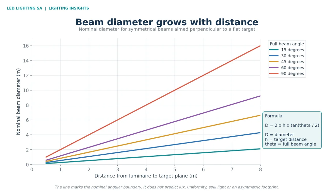 Figure 3. Nominal beam diameter grows linearly with target distance, but the rate of growth changes significantly with the full beam angle.
Mounting height changes the result
The same optic creates a larger beam diameter as the distance to the target increases.
A 30-degree beam creates a nominal diameter of about 1.61 metres at 3 metres, but about 3.22 metres at 6 metres. The angle has not changed; the geometry has.
At the same time, illuminance reduces with distance. For an ideal point source aimed perpendicular to a surface:
Illuminance in lux = luminous intensity in candela / distance squared
Doubling the distance therefore reduces the on-axis illuminance to approximately one quarter, assuming the same intensity and no other contributions.
This creates a central design trade-off:
- A greater mounting distance increases the size of the beam footprint.
- The same distance reduces the illuminance delivered to the target.
- A narrower optic may restore intensity but can reduce coverage and uniformity.
- A wider optic may improve coverage but lower centre-beam intensity.
Mounting height, output, optic and spacing must therefore be selected as a connected system.
Why the same lumens can create very different intensity
Lumens describe total visible light output. Beam angle describes how that output is distributed around an axis. Candela describes the intensity in a particular direction, and lux describes the illuminance arriving at a surface.
If an idealised 1,500 lumens were distributed uniformly inside a circular cone, narrowing that cone would concentrate the output dramatically.
At a distance of four metres, the simplified comparison would be approximately:
- 15-degree cone:05 m diameter, 27,900 cd and 1,744 lux on axis
- 30-degree cone:14 m diameter, 7,000 cd and 438 lux on axis
- 60-degree cone:62 m diameter, 1,780 cd and 111 lux on axis
- 90-degree cone:00 m diameter, 815 cd and 51 lux on axis
These values are conceptual, not product predictions. Real beam angles are defined at the 50% intensity points; real luminaires do not distribute every lumen uniformly inside the nominal cone, and a portion of the output may lie outside it.
The example demonstrates the principle: the same total output can produce very different intensity and coverage when the optical distribution changes.
This is why lumens and wattage alone cannot tell us whether a luminaire will light the intended surface correctly.
 Figure 4. Conceptual uniform-cone comparison: the same 1,500 lumens create very different beam diameters, candela values and on-axis lux when the distribution changes.
Symmetrical, oval and asymmetric distributions
Many introductory diagrams show a circular cone, but real projects often require different shapes.
Symmetrical beams
A symmetrical optic has a similar spread in every radial direction. It generally creates a circular footprint when aimed perpendicular to a flat surface.
This can suit downlights, spotlights and open areas where equal spread around the axis is useful.
Oval or two-axis beams
A luminaire described as 30 x 60 degrees has different spreads in two perpendicular planes. The footprint is typically oval when the luminaire is aimed normally at a surface.
This can place light efficiently along:
- Retail shelving
- Warehouse aisles
- Long tables
- Facades and signs
- Corridors and pathways
The orientation of the optic matters. Rotating an oval beam by 90 degrees can change the project result completely.
Asymmetric distributions
An asymmetric optic intentionally throws more light in one direction than another. It is often more useful than a tilted symmetrical flood because it can place light forward while controlling backlight, uplight or glare.
Applications include roadways, car parks, perimeter lighting, wall washing, sports areas and specialised industrial layouts.
A single beam-angle number is rarely enough to describe these distributions. Review the polar curve, intensity table and IES or LDT file.
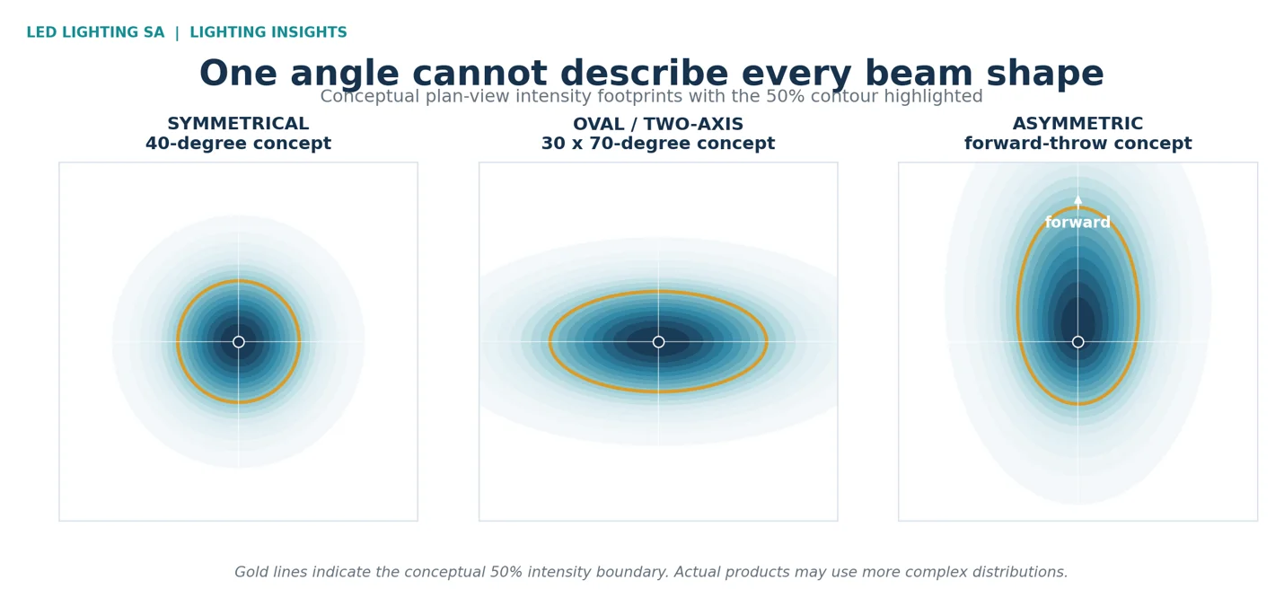 Figure 5. Conceptual plan-view footprints show why a circular beam angle, a two-axis angle and an asymmetric forward throw must be read differently.
Beam overlap and uniformity
Lighting layouts normally use multiple luminaires, so the visible result depends on how their distributions combine.
If fittings are spaced too far apart, narrow beams can create bright islands separated by dark areas. If they are too close, the overlap may create excessive peaks, wasted light or unnecessary fittings.
There is no universal overlap percentage that guarantees a good design. The answer depends on:
- The complete intensity distribution, not only the 50% boundary
- Mounting height and spacing
- Surface reflectance and room inter-reflection
- The required average and minimum illuminance
- The permitted uniformity ratio
- The position and orientation of the task plane
- Obstructions, shelving, equipment and partitions
- Contributions from adjacent fittings and daylight
A sensible first estimate can use beam diameter to test whether the spacing is plausible. The final decision should use verified photometric data in the actual project model.
Uniformity must also be checked where it matters. A warehouse floor, vertical rack face, production bench and inspection surface may each need a separate calculation grid.
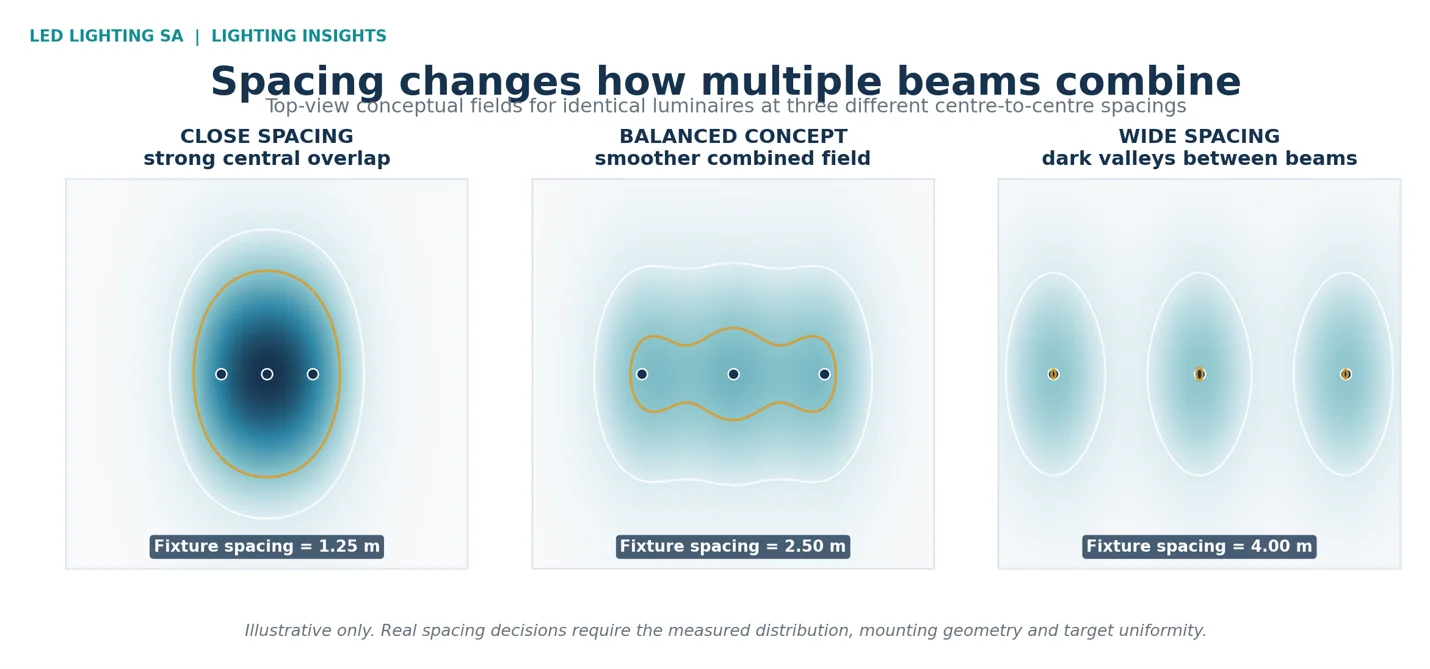 Figure 6. Conceptual top views illustrate strong overlap, a smoother combined field and dark valleys as identical luminaires are moved farther apart.
Beam angle, contrast and visual hierarchy
Not every space should be uniformly bright.
In retail, hospitality, galleries and experience-led environments, narrow or medium beams can create focal points while broader layers provide ambient context. This contrast guides attention, reveals texture and gives the space depth.
The ratio between the focal light and the surrounding illumination often matters more than the beam angle by itself. A narrow beam aimed at an already bright surface may have little visual impact, while a modest accent can appear dramatic in a darker environment.
Successful layered lighting may combine:
- Broad ambient illumination for orientation
- Controlled task lighting for performance
- Narrow accent beams for emphasis
- Vertical light for faces, products and spatial brightness
- Decorative light for identity and atmosphere
The optic should support the intended visual hierarchy without creating discomfort or unnecessary energy use.
Beam angle is not a glare rating
A narrow beam can keep light away from unwanted areas, but it can also create high intensity and strong contrast. A wide beam can soften coverage, but it may expose bright optical surfaces to more viewing positions.
Glare depends on more than beam angle. It can be affected by:
- Source luminance and apparent source size
- Shielding, cutoff and recess depth
- Viewing direction and observer position
- Background luminance and contrast
- Mounting height and aiming
- The number and arrangement of luminaires
- Reflections from glossy materials
Similarly, a narrow beam does not automatically prevent light spill. Poor aiming can send a precise beam into the wrong place. Exterior designs should consider backlight, uplight, glare, site boundaries and environmental requirements as part of the complete distribution.
Beam control is valuable, but visual comfort and obtrusive-light control require a full photometric review.
A practical application guide
| Application | Useful optical starting point | Also verify |
| Retail and showroom accents | Narrow to medium beam, often 10-40 degrees | Merchandise size, aiming, contrast, colour quality, spill, flexibility and glare |
| Hospitality tables and features | Narrow or medium controlled beam | Mounting distance, dimming, facial light, atmosphere, edge softness and visual comfort |
| Offices, classrooms and general interiors | Broad, glare-managed or batwing distribution | Task-plane lux, uniformity, vertical light, UGR or relevant glare criteria, controls and daylight |
| Warehouses and open industrial areas | Medium to wide high-bay optics selected for mounting height | Floor and task-plane lux, uniformity, obstructions, dirt, emergency lighting and maintenance |
| Warehouse aisles and racking | Narrower or oval distribution aligned to the aisle | Vertical rack-face light, orientation, spacing, forklift routes, glare and shadowing |
| Facades, signs and architectural features | Narrow, medium, oval or asymmetric optic matched to target geometry | Aiming, setback, spill, surface reflectance, texture, maintenance and environmental limits |
| Roads, yards and car parks | Purpose-designed asymmetric distribution | Horizontal and vertical illuminance, uniformity, glare, backlight, uplight, boundaries and pole geometry |
| Rail, transport and specialist systems | Project-specific controlled distribution | Viewing direction, redundancy, vibration, compliance, maintainability and environmental conditions |
These are starting points, not universal specifications. The correct optic depends on the project geometry, visual task, risk profile and applicable standards.
How to read a product data sheet
When beam control matters, look beyond the headline angle.
1. Confirm the angle definition
Check whether the stated value uses the 50% intensity points, a 10% field boundary or another convention.
2. Check both axes
For an oval or asymmetric beam, confirm the horizontal and vertical distributions and how the optic must be oriented after installation.
3. Review centre beam intensity
Peak or centre beam candela helps indicate how strongly the luminaire projects light on axis. It must still be interpreted with distance, aiming and the rest of the distribution.
4. Compare luminaire lumens
Use output measured for the complete fitting rather than theoretical LED-package lumens. Optical efficiency and system losses affect the available light.
5. Read the polar intensity curve
The curve reveals whether the distribution is narrow, broad, asymmetric, batwing-shaped or different across the measured planes.
6. Request the photometric file
An IES or LDT file allows the measured distribution to be placed into a model of the real project. ANSI/IES LM-63 defines a standard format for electronically transferring photometric data, while goniophotometric testing records the directional distribution around the luminaire.
7. Check the installed orientation
A correct photometric file can still produce an incorrect design if the fitting is rotated, tilted or mounted differently from the model.
Common beam-angle mistakes
Treating the beam edge as a hard boundary
The nominal angle marks a threshold, not the point where all light ends. Spill and field light continue beyond it.
Choosing by wattage or lumens alone
Electrical power and total output do not describe where the light goes. Optics determine concentration and distribution.
Ignoring the target-plane distance
Use the distance from the luminaire to the actual surface being lit, not a generic room height.
Using one optic throughout a project
Open areas, aisles, displays, task surfaces and circulation routes may require different distributions.
Assuming every beam is circular
Many effective luminaires use oval, batwing or asymmetric optics. Check both measured planes and the intended orientation.
Using catalogue photography as photometric evidence
Exposure, camera position, surface reflectance and post-processing can change how a beam looks. Use measured data for design.
Skipping a glare and spill review
The right footprint can still be uncomfortable or environmentally inappropriate if source visibility, aiming and cutoff are wrong.
Modelling with the wrong file or rotation
Product variants may have different optics. Confirm the exact photometric file, output, orientation and mounting condition.
Frequently asked questions
Does a wider beam angle produce more light?
Not necessarily. Beam angle describes distribution, while lumens describe total output. A wider optic usually spreads the available light over a larger area and may reduce peak intensity, but the total luminaire lumens depend on the complete optical and electrical system.
Can beam angle be converted directly to lux?
No. You also need luminous intensity in the relevant direction, distance, incidence angle and the complete distribution. For an ideal point source aimed perpendicular to a surface, on-axis lux can be approximated as candela divided by distance squared.
What is the best beam angle for a room?
There is no universal best value. The answer depends on ceiling height, fixture spacing, room dimensions, surface reflectance, the target plane, glare control and the intended visual effect.
What does a 30 x 60-degree beam mean?
It indicates different nominal spreads in two perpendicular planes. The resulting footprint is usually oval rather than circular, and the optic’s installed orientation is critical.
Does a narrower beam travel farther?
All light reduces in illuminance with distance, but a narrower optic can produce higher luminous intensity in the target direction. This can maintain more useful lux at a distant surface than a wider optic with similar total output.
Can the beam angle be changed after installation?
Only if the product is designed for interchangeable optics, adjustable reflectors or a zoom mechanism. Otherwise, changing the distribution normally requires a different lens, reflector or luminaire.
Is beam angle the same as cutoff angle?
No. Beam angle describes the width of the main intensity distribution. Cutoff and shielding describe how the luminaire limits light at certain viewing or emission angles, often to manage glare or unwanted light.
Is a narrow beam always more efficient?
It can place a greater proportion of light onto a small target, but it is not automatically the most efficient solution for a whole space. If the beam is too narrow, more fittings may be needed to achieve coverage and uniformity.
A better way to choose an optic
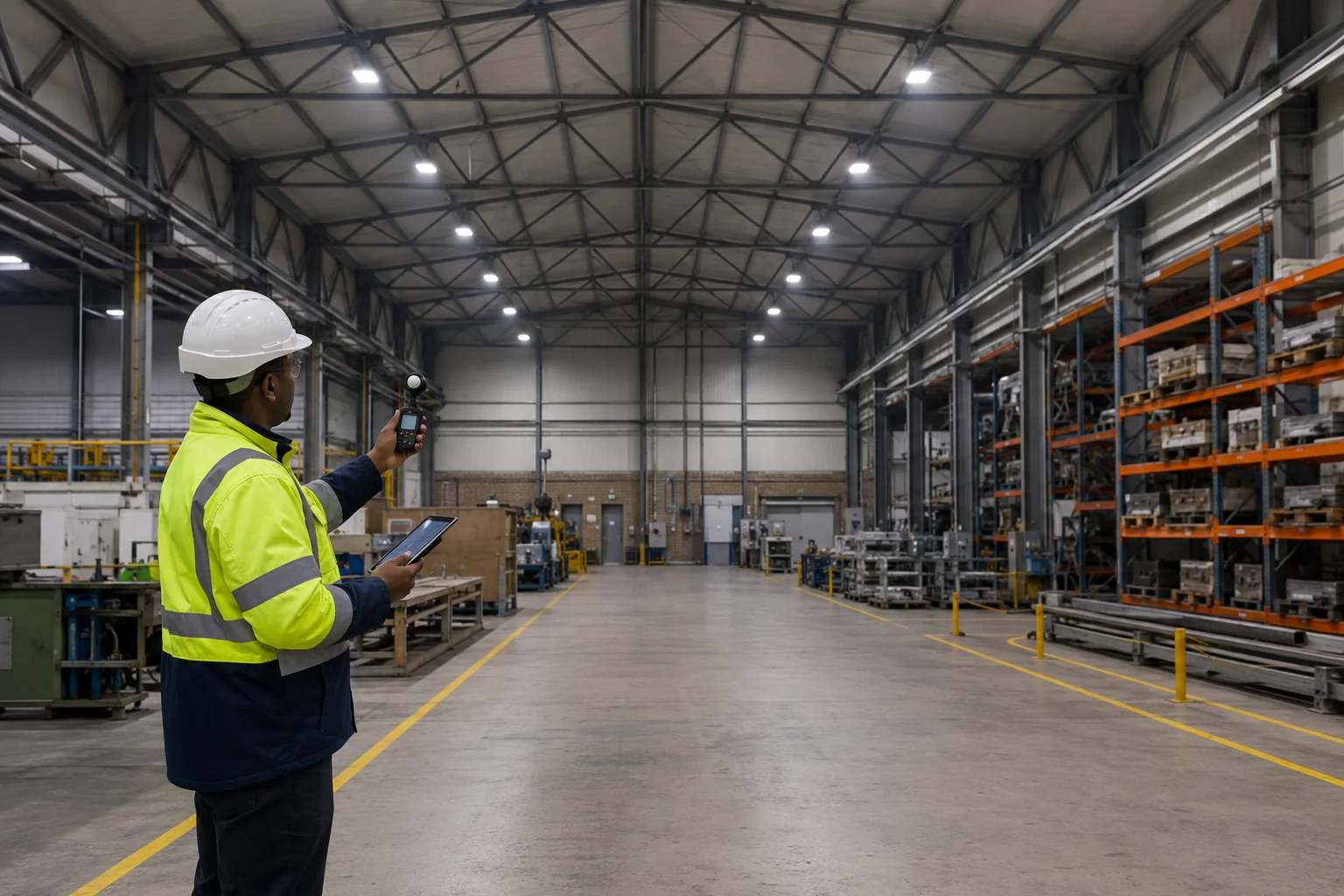 Figure 7. A site survey begins by confirming mounting height, luminaire position and real geometry; commissioning measurements should then be taken at the relevant task planes.
1. Define the visual task
Identify what must be seen, the size and position of the target, and whether the design needs uniformity, contrast or both.
2. Measure the real geometry
Confirm mounting positions, target-plane heights, setbacks, aiming angles, obstructions and the orientation of key surfaces.
3. Select a plausible distribution
Use beam diameter as an early geometry check, then choose a symmetrical, oval, asymmetric or diffuse optic that suits the target.
4. Model the exact product
Use the correct IES or LDT file, output option and installed orientation in a photometric model of the project.
5. Review more than average lux
Check minimum and maximum values, uniformity, vertical light, contrast, glare, spill and other application-specific criteria.
6. Coordinate the installation
Document aiming and rotation clearly. A well-designed oval or asymmetric distribution can fail if installed in the wrong orientation.
7. Commission the result
Inspect the completed installation, confirm aiming and take structured measurements at the correct planes where required.
Better beam control creates better lighting
Beam angle is a simple number with a significant influence on how a space looks and performs.
It helps us understand whether light will be concentrated or broadly distributed, and it provides a useful first estimate of the beam footprint at a given distance. But the number becomes meaningful only when it is connected to candela, lumens, lux, mounting geometry, photometric data and the intended visual task.
At LED Lighting SA, our design and engineering teams consider the complete journey of light – from LED source and optical system to the architecture, working plane and people using the space. We use photometric layouts, 3D modelling, product engineering and application knowledge to select distributions that balance coverage, intensity, uniformity, comfort and visual impact.
Because successful lighting is not simply about producing light. It is about shaping it deliberately and placing it where it adds value.
Speak to the LED Lighting SA team about optic selection, a photometric layout or a project-specific lighting solution for your commercial, retail, industrial, hospitality, transport or specialist application.
Technical references
- LEDVANCE – Understanding Light Beam Angles
- CIE International Lighting Vocabulary – Beam angle
- CIE International Lighting Vocabulary – Centre beam intensity
- CIE International Lighting Vocabulary – Beam spread
- ERCO Lighting Knowledge – Emission angle
- ERCO Lighting Knowledge – Light beam diameter
- Illuminating Engineering Society – ANSI/IES LM-75-19 goniophotometry guide
- Illuminating Engineering Society – ANSI/IES LM-63-19(R25) photometric data format